Inside a NetApp controller: device architecture
-
Phase 0: Start here
-
Phase 1: Architecture and foundation
-
Phase 2: Protocols and day-to-day administration
-
Phase 3: Data protection and enterprise integrations
-
Phase 4: Troubleshooting blueprint
-
Phase 5: Final project and career
Lesson 6 showed you the families of NetApp systems from the outside. This deep dive on NetApp controller architecture opens the lid: what sits inside one controller, how two controllers in an HA pair talk, and how a write travels from the network port down to a drive.
You don’t need this to create a volume. You do need it the day a field engineer asks “which slot is the NVRAM card in?”, or a shelf shows single-path and you have to explain why that matters.
Where this page fits
Deep dive in NetApp ONTAP Storage Administration · Phase 1, Architecture and foundation · Before this: Lesson 6, AFF, FAS and ASA hardware · Next: NetApp platform models and specs
| Time | You need | By the end you can |
|---|---|---|
| 45 minutes | The practice shell from Lesson 2 | Name every major part of a controller, read the hardware views in the CLI, and explain where a write goes before it reaches disk |
What it is, in one line
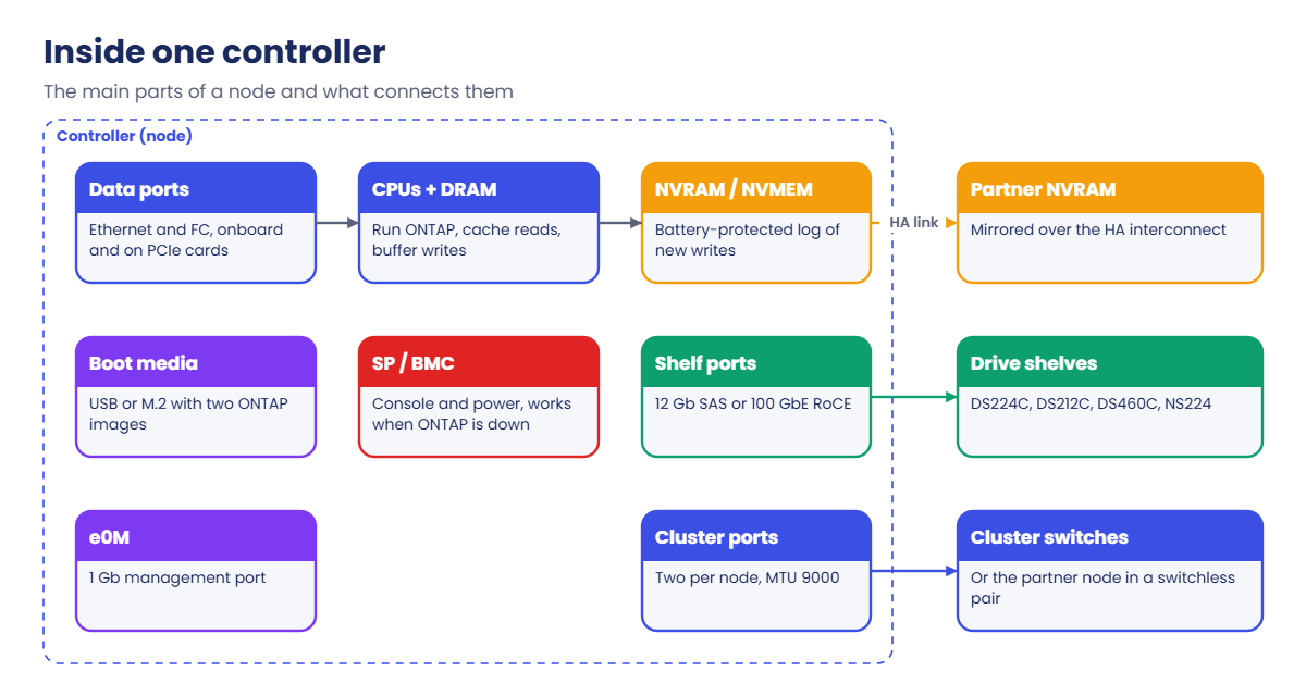
A NetApp controller is a purpose-built server, with CPUs, memory, a battery-protected write log, boot media and I/O slots, and two of them form an HA pair that shares the same drives.
In Simple Words
Two cashiers and one shared ledger
Picture a busy shop with two cashiers at one counter. Each cashier writes every sale in a small notebook, and also calls out the sale so the other cashier copies it into their notebook. Once an hour, both notebooks are copied neatly into the big shop ledger in the back room.
If one cashier faints, the other already has a copy of every sale since the last copy into the ledger, so nothing is lost and the queue keeps moving. A NetApp HA pair works the same way: the notebook is NVRAM, the calling out is the HA interconnect, and the ledger is the drives.
Engineer's View
What is inside one node
Each controller (node) has multi-core Intel CPUs, DRAM for the operating system and read/write cache, and a protected write log. Bigger systems use a separate NVRAM card or module with its own battery; entry systems use NVMEM, a battery-protected part of main memory whose contents are written to the boot media if power is lost.
ONTAP itself boots from internal boot media (a USB key or an M.2 SSD, depending on the model), which holds two ONTAP images so an upgrade can fall back. PCIe slots take I/O modules for Ethernet, Fibre Channel, SAS or NVMe shelf ports, and the onboard ports include e0M for management.
A Service Processor (SP) on older models, or a baseboard management controller (BMC) on newer ones, runs even when ONTAP is down, so you can reach the console and power-cycle the node remotely. Power supplies, fans and the controllers themselves are redundant and hot-swappable.
How it works, step by step
1The parts of a controller
Every node, from the small FAS2820 to the AFF A90, has the same building blocks. Only the numbers change: more cores, more memory, more slots.
| Part | What it does | What you see in the CLI |
|---|---|---|
| CPUs and DRAM | Run ONTAP, cache reads, buffer writes before they go to disk | system node show (model), sysstat -M (CPU) |
| NVRAM or NVMEM | Battery-protected log of every write that has not reached disk yet | Errors about the battery in the event log |
| Boot media | USB key or M.2 SSD with two ONTAP images | version, system image show |
| PCIe I/O modules | Extra Ethernet, FC, SAS or NVMe/RoCE ports | network port show, network fcp adapter show |
| Onboard ports | e0M for management, cluster ports, data ports, SAS ports | network port show |
| SP or BMC | Out-of-band console and power control | system node service-processor show |
| PSUs and fans | Redundant power and cooling, hot-swappable | event log show, Config Advisor |
2Chassis: single or dual, internal drives or not
Two controllers can share one chassis (a single-chassis HA pair) or sit in two separate chassis (a dual-chassis HA pair). The FAS2820, AFF A20, A30, A50, A70 and A90 are single-chassis; the AFF A1K, FAS70 and FAS90 put one controller in each 2U chassis.
Some chassis also hold drives. The FAS2820 has 12 drive slots, the AFF A20, A30 and A50 have 24, and the AFF A70 and A90 have 48 in a 4U enclosure. Others, like the AFF A400, A1K and FAS90, keep all drives in external shelves.
In a single-chassis pair the HA interconnect runs across the chassis midplane, so there are no HA cables to plug. In a dual-chassis pair the HA link uses cables between the chassis, and on several current models it shares the high-speed cluster ports; the installation guide for your model shows exactly which ports.
3Shelves and how they are cabled
When the internal bays are full, you add shelves. There are two cabling worlds: SAS shelves with IOM modules, and NVMe shelves that talk RDMA over Ethernet (RoCE).
| Shelf | Size and drives | Module | Connects with |
|---|---|---|---|
| DS224C | 2U, 24 small (2.5-inch) SAS drives, HDD or SSD | IOM12 (A and B) | 12 Gb SAS cables in stacks |
| DS212C | 2U, 12 large (3.5-inch) SAS drives | IOM12 (A and B) | 12 Gb SAS cables in stacks |
| DS460C | 4U, 60 large drives in drawers | IOM12 (A and B) | 12 Gb SAS cables in stacks |
| NS224 | 2U, 24 NVMe SSDs | NSM100 or NSM100B (A and B) | 100 GbE RoCE ports on both controllers |
Each shelf has two modules, A and B, and every controller in the HA pair needs a path through both. For SAS this is called multipath HA cabling: each stack is cabled to both controllers, and each controller reaches the stack through IOM A and IOM B. Shelf IDs must be unique within the HA pair, which is why the shell’s shelves are 1.0 and 1.1.
A SAS stack can hold up to 10 shelves, except DS460C (up to 4 per stack) and the older DS4486 (up to 5). A stack that mixes shelf types stops at 240 drives or 10 shelves, whichever comes first, according to NetApp’s knowledge base article on shelf limits in SAS stacks.
Get this wrong and the system still works, until one cable or module fails. That’s why NetApp’s Config Advisor tool checks cabling after every install.
4The life of a write, through the hardware
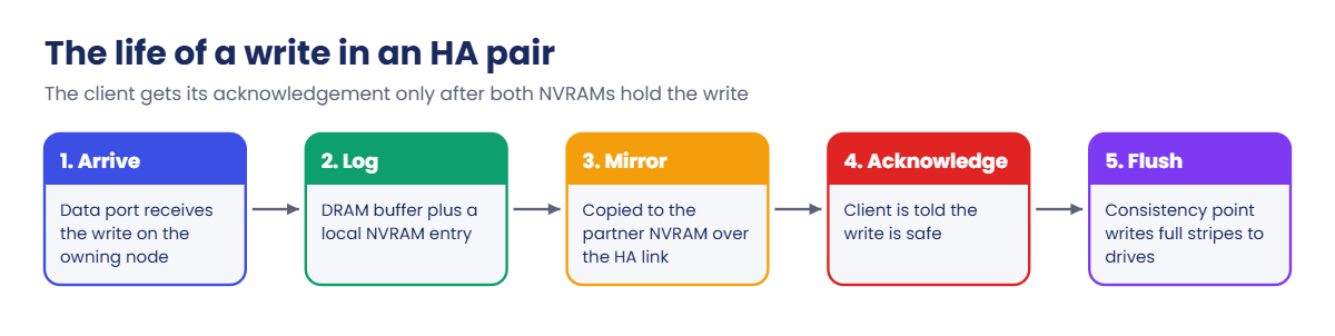
Follow one write from a client to the drives and you touch almost every part above:
- The write arrives on a data port (onboard or a PCIe NIC or FC card) and reaches the node that owns the volume.
- ONTAP puts the data in DRAM and logs it in NVRAM.
- The same log entry is copied over the HA interconnect into the partner’s NVRAM.
- Only now does the client get its acknowledgement, so the write is safe even if this node dies a second later.
- At a consistency point (about every 10 seconds, or sooner when the log fills), WAFL writes the buffered data as full RAID stripes through the SAS or NVMe ports to the drives.
If the node fails between steps 4 and 5, the partner takes over and replays the log from its own NVRAM copy. Lesson 14 covers WAFL and NVRAM in more depth.
Hands-on lab: read the hardware from the CLI
Before you run any command, double-check it
Read every command twice before you press Enter. Check the target: the server name, the user, the disk or device name, the path and the sizes. These commands are for learning and were tested in our lab, not on your system. At work, run the read-only commands first, follow your change process, make sure a backup exists, and ask a second person to check anything that changes or deletes data. You run them at your own risk.
This lab uses the SaatVedha ONTAP practice shell, our own learning tool. It is not NetApp software: real ONTAP output looks like this but is not identical.
A real controller lives in a data centre, but ONTAP describes its hardware through the CLI, and so does the practice shell. Start from a clean lab with python ontapsim.py -c "simctl reset", then log in.
1Identify the node
system node show -node saat-cluster-01 -instanceYou should see this:
Node: saat-cluster-01
Owner: -
Location: Rack A1
Model: FAS8300
Serial Number: 721500001001
System ID: 0530003003
Vendor: NetApp
Health: true
Eligibility: true
Uptime: 12 days 00:00
Partner: saat-cluster-02
Product Version: NetApp Release 9.18.1Model, serial number and System ID are the three things NetApp support asks for first. The System ID also owns the disks, which is how ONTAP knows which drives belong to this node.
✅ Checkpoint: You can read the model, serial number and partner of saat-cluster-01.
2Look at the shelves and drives
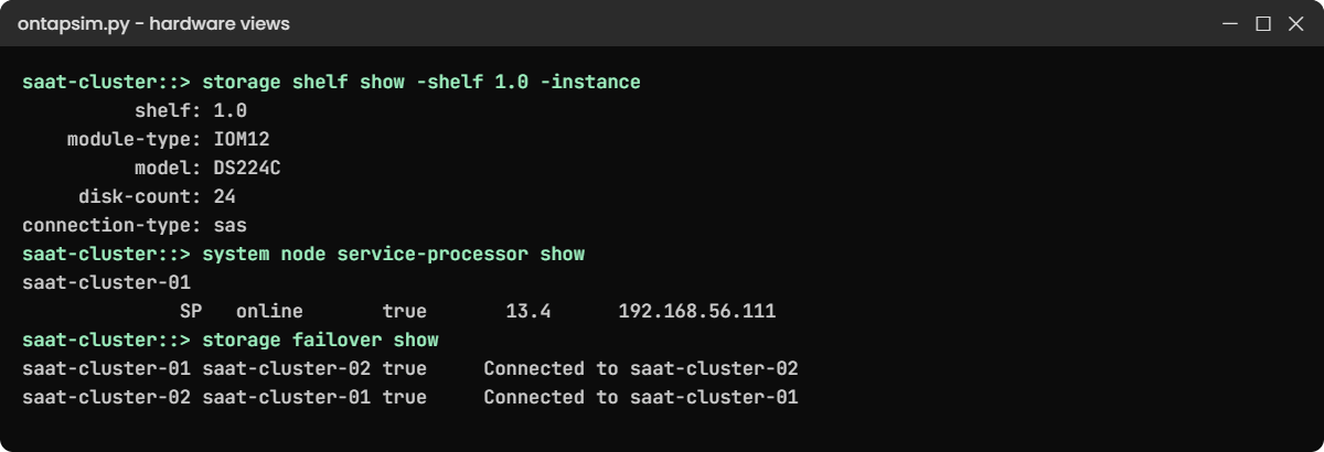
storage shelf show -shelf 1.0 -instance
storage disk show -disk 1.0.0 -fields model,serial-number,type,owner
storage disk show -disk 1.1.0 -fields model,serial-number,type,ownerYou should see this:
shelf: 1.0
shelf-name: 1.0
shelf-id: 0
serial-number: SHFMS100110
module-type: IOM12
model: DS224C
disk-count: 24
state: online
connection-type: sas
stack-id: 1
saat-cluster::> storage disk show -disk 1.0.0 -fields model,serial-number,type,owner
disk model serial-number type owner
----- ---------------- ------------- ---- ---------------
1.0.0 X425_HCBFE1T8A10 SV62DAC96F SAS saat-cluster-01
saat-cluster::> storage disk show -disk 1.1.0 -fields model,serial-number,type,owner
disk model serial-number type owner
----- ---------------- ------------- ---- ---------------
1.1.0 X357_S16433T8ATE SVF855AA3C SSD saat-cluster-01The lab has one SAS stack with two DS224C shelves, each with IOM12 modules. The X-number in the drive model is the NetApp part number you order a replacement by.
✅ Checkpoint: You can say which shelf model, module type and drive types the lab uses.
3Map the ports
network port show -node saat-cluster-01You should see this:
Node: saat-cluster-01
Ignore
Speed(Mbps) Health Health
Port IPspace Broadcast Domain Link MTU Admin/Oper Status Status
--------- ------------ ---------------- ---- ---- ----------- -------- ------
e0a Cluster Cluster up 9000 auto/10000 healthy false
e0b Cluster Cluster up 9000 auto/10000 healthy false
e0c Default Default up 1500 auto/10000 healthy false
e0d Default Default up 1500 auto/10000 healthy false
e0e Default Default up 1500 auto/10000 healthy false
e0f Default Default up 1500 auto/10000 healthy false
e0M Default Default up 1500 auto/1000 healthy false
7 entries were displayed.Port names tell you where the port is: e0a is Ethernet, slot 0 (onboard), port a. A port in a PCIe card in slot 3 would be e3a. e0a and e0b sit in the Cluster IPspace with MTU 9000, so they are the cluster interconnect ports, and e0M is the 1 Gb management port.
✅ Checkpoint: You can point to the cluster ports and the management port.
4Check the out-of-band controller and HA
system node service-processor show
cluster ha show
storage failover showYou should see this:
IP Firmware
Node Type Status Configured Version IP Address
------------- ---- ------------ ---------- --------- -------------------------
saat-cluster-01
SP online true 13.4 192.168.56.111
saat-cluster-02
SP online true 13.4 192.168.56.112
2 entries were displayed.
saat-cluster::> cluster ha show
High-Availability Configured: true
High-Availability Backend Configured (MBX): true
saat-cluster::> storage failover show
Takeover
Node Partner Possible State Description
--------------- --------------- -------- -------------------------------------
saat-cluster-01 saat-cluster-02 true Connected to saat-cluster-02
saat-cluster-02 saat-cluster-01 true Connected to saat-cluster-01
2 entries were displayed.Type SP means a Service Processor; newer models show BMC here. “Connected to saat-cluster-02” means the HA interconnect is up and NVRAM is being mirrored, which is what makes takeover possible.
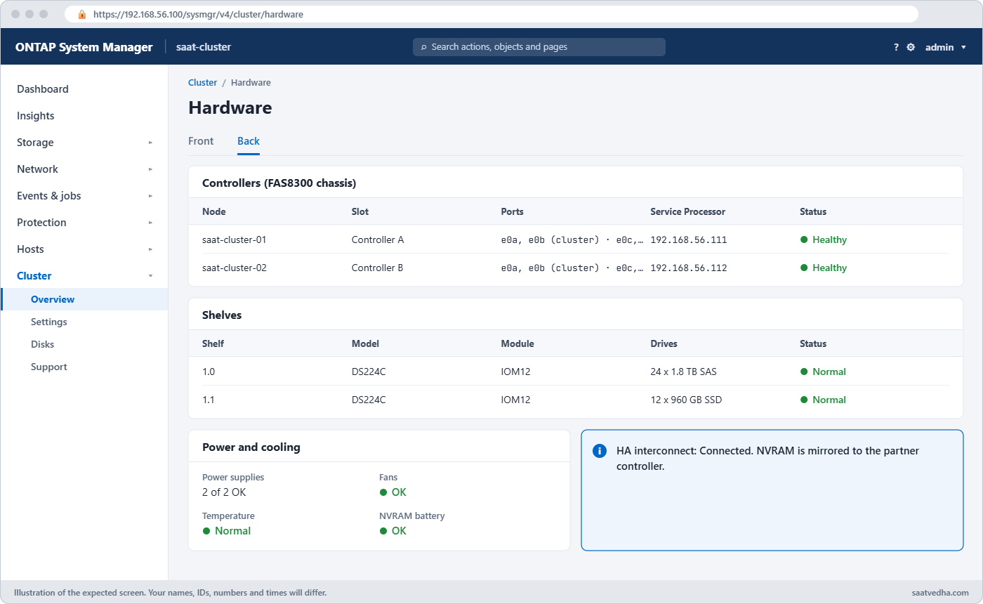
In System Manager you find the same hardware under Cluster › Hardware, which draws the front and back of each chassis and shelf.
✅ Checkpoint: Both nodes show an SP online and Takeover Possible true.
Break It, Then Fix It
Two hardware faults that every admin meets sooner or later. Cause each one, read it from the CLI, then clear it.
1The HA interconnect goes down
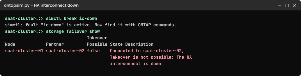
simctl break ic-down
storage failover showYou’ll get this:
simctl: fault "ic-down" is active. Now find it with ONTAP commands.
saat-cluster::> storage failover show
Takeover
Node Partner Possible State Description
--------------- --------------- -------- -------------------------------------
saat-cluster-01 saat-cluster-02 false Connected to saat-cluster-02,
Takeover is not possible: The HA
interconnect is down
saat-cluster-02 saat-cluster-01 false Connected to saat-cluster-01,
Takeover is not possible: The HA
interconnect is down
2 entries were displayed.Data still flows, but NVRAM is no longer mirrored, so if a node fails now the partner can’t take over safely. On a single-chassis system this usually means a controller or midplane problem; on a dual-chassis system check the HA cables and ports first. Open a case, and don’t plan any maintenance until it shows true again.
Clear it with simctl fix ic-down.
✅ Checkpoint: After the fix, Takeover Possible is true on both nodes.
2A cluster port loses link
simctl break port-down saat-cluster-01 e0a
network port show -node saat-cluster-01
network interface show -vserver ClusterYou’ll get this:
Port IPspace Broadcast Domain Link MTU Admin/Oper Status Status
--------- ------------ ---------------- ---- ---- ----------- -------- ------
e0a Cluster Cluster down 9000 auto/- healthy false
e0b Cluster Cluster up 9000 auto/10000 healthy false
...
Cluster
saat-cluster-01_clus1
up/down 169.254.10.20/16 saat-cluster-01 e0a true
saat-cluster-01_clus2
up/up 169.254.10.21/16 saat-cluster-01 e0b trueEach node has two cluster ports, so the cluster stays up on e0b, but you’ve lost your redundancy. Check the cable and SFP on e0a and the port on the cluster switch (or the partner node, in a switchless pair). On real ONTAP the cluster LIF also moves over to e0b; the practice shell leaves it on e0a with Oper down, which is just as easy to spot.
Clear it with simctl fix port-down.
✅ Checkpoint: After the fix, all four cluster LIFs show up/up.
This happened at work
The two-hour drive to press one key
A hospital group in Kozhikode ran its imaging archive on a FAS pair in a data centre about 60 km from the main campus. The Service Processors had never been given IP addresses, because “we’ll do it later” during the install, and later never came.
One night a node’s boot media failed after a planned reboot, and the node stopped at the boot loader. The partner had taken over, so the archive stayed online, but the on-call admin couldn’t see the console from home and the only way in was a serial cable in the rack. He drove two hours to reach the data centre, where support walked him through the boot media replacement and recovery steps.
The next Monday the team configured every SP on the management network and tested ssh admin@SP-IP followed by system console from the jump host. The boot media was replaced under a support case, and the rule now is that no install is signed off until the SP or BMC answers remotely.
Common mistakes and troubleshooting
| Mistake | What happens | Do this instead |
|---|---|---|
| Cabling a shelf stack through only one IOM | It works until that module or cable fails, then the whole stack drops | Cable multipath HA: each controller through IOM A and IOM B, then run Config Advisor |
| Ignoring a “takeover not possible” state | A node failure becomes an outage instead of a takeover | Treat Takeover Possible false as urgent and fix the HA link first |
| Pulling the wrong controller during a part swap | You take down the healthy node | Check the serial number and use the locate LED before you touch anything |
| Reusing shelf IDs in one HA pair | Disk names clash and ONTAP reports duplicate shelf IDs | Give every shelf in the pair a unique ID before you cable it |
| Forgetting the SP or BMC network | No remote console when ONTAP hangs at night | Give every SP/BMC an IP on the management network on day one |
Interview questions
Click a question to open it. Each one is written the way an interviewer would ask it. Under it you will see why they ask it and one way you could answer, in your own words.
Fresher level
1. Can you tell me, in simple words, what is inside a NetApp controller?
Why they ask this: They want to see that you think of a controller as real hardware, not a black box.
How you might answer: It’s a purpose-built server: CPUs, memory, a battery-protected write log called NVRAM, boot media with ONTAP on it, and PCIe slots for network, FC and shelf ports. It also has a Service Processor or BMC so I can reach the console even if ONTAP is down.
2. What is the HA interconnect used for?
Why they ask this: They’re checking that you understand why an HA pair can take over without losing data.
How you might answer: Each node copies its NVRAM write log to the partner over the HA interconnect before it acknowledges a write. If one node fails, the partner already has those writes and replays them during takeover. I check it with storage failover show; Takeover Possible should be true.
2–5 years experience
3. A field engineer says shelf 2.3 is cabled single-path. Why does that matter if everything works?
Why they ask this: They want to see that you understand redundancy and don’t wait for an outage.
How you might answer: It means only one IOM or cable connects that stack to the controllers, so one failed part takes every drive in the stack offline for both nodes. I’d plan a slot to add the second path through IOM B and confirm it with Config Advisor afterwards.
4. How would you find the model, serial number and System ID of a node before opening a case?
Why they ask this: They’re checking whether you know the basic data support always asks for.
How you might answer: I’d run system node show -node with -instance, which shows model, serial number and System ID. For drives I’d use storage disk show -fields model,serial-number, and I’d attach an AutoSupport so support has the full hardware list.
Senior level
5. What changes in your planning between a single-chassis and a dual-chassis HA pair?
Why they ask this: They want to see that you think about rack space, cabling and failure domains.
How you might answer: With a single chassis the HA link is inside the box, so there are fewer cables but one chassis holds both controllers. With dual chassis I plan rack space for two units, HA and cluster cabling between them, and I can place them so one chassis problem doesn’t touch the other. Either way I follow the model’s installation guide for the exact ports.
6. An NVRAM battery warning shows up on a Friday evening. What do you do?
Why they ask this: They want to see how you weigh risk, timing and the vendor process.
How you might answer: I’d check the event log for the exact message and how long the battery is expected to last, and make sure takeover is still possible. Then I’d open a case and get the part sent, because NVRAM protects writes that haven’t reached disk yet. If support advises it, I’d plan a takeover and swap rather than wait for the weekend to end.
Quick quiz
Q1. What does NVRAM hold?
- The ONTAP software image
- A log of writes that haven’t reached disk yet
- The cluster database
- Read cache only
Show answer
B — NVRAM (or NVMEM) logs every acknowledged write until the next consistency point.
Q2. Which tool lets you reach the node console when ONTAP is down?
- System Manager
- The SP or BMC
- AutoSupport
- Config Advisor
Show answer
B — the Service Processor or baseboard management controller runs independently of ONTAP.
Q3. What does port name e3a mean?
- Ethernet, slot 3, port a
- Expansion shelf 3, bay a
- Error port 3
- Cluster port 3
Show answer
A — e = Ethernet, the number is the slot (0 = onboard) and the letter is the port.
Q4. How does an NS224 shelf connect to the controllers?
- 12 Gb SAS cables
- Fibre Channel
- 100 GbE RoCE ports
- USB
Show answer
C — NS224 uses NVMe over RDMA on 100 GbE ports through its NSM modules.
Q5. What does “Takeover Possible: false” usually point to first?
- A full aggregate
- The HA interconnect or partner state
- A missing licence
- A slow LIF
Show answer
B — takeover needs a healthy HA link so NVRAM is mirrored.
Quick recap
- A controller is a server with CPUs, DRAM, NVRAM or NVMEM, boot media, PCIe I/O and an SP or BMC.
- Two controllers form an HA pair in one chassis or two; the HA interconnect mirrors NVRAM.
- SAS shelves (DS224C, DS212C, DS460C) use IOM12 modules; NS224 uses NSM modules over RoCE.
- Cable every shelf through both modules to both controllers, and check with Config Advisor.
- A write is safe once it is in both NVRAMs; WAFL writes it to drives at the next consistency point.
What’s next
Next, see every current and recent model side by side in NetApp platform models and specs, then carry on with Lesson 7, Cluster setup.
Further reading: NetApp controller architecture
Want to go deeper into NetApp controller architecture? NetApp’s AFF A20, A30 and A50 system documentation shows a current controller, its ports and its key specifications, and the SAS shelf cabling rules explain multipath HA cabling in detail. For any model, NetApp Hardware Universe is the final word on parts and limits.
You can also see the full plan for this course on the NetApp ONTAP Storage Administration course page.
